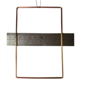
Hollow inductor coils are commonly used electronic components. When current flows through the wires of a hollow inductor coil, it generates a certain electromagnetic field around the wires, inducing an electromotive force known as self-inductance. This phenomenon is called electromagnetic induction. To enhance the effect of electromagnetic induction, the insulated metal wire of the hollow inductor coil can be wound into a certain number of turns, forming the coil. The main characteristics and parameters of hollow inductor coils are as follows:

Inductance (L): Inductance represents the inherent characteristics of the hollow inductor coil itself and is independent of the current. Unless it is a special type of inductor coil (color-coded inductors), the inductance value is generally not explicitly marked on the coil but is indicated by a specific name.
Reactance (XL): Reactance is the resistance of the hollow inductor coil to alternating current and is measured in ohms. The relationship between inductance (L) and the alternating frequency (f) is given by XL = 2πfL.
Quality Factor (Q): The quality factor represents the quality of the coil and is defined as the ratio of reactance (XL) to its equivalent resistance (R), i.e., Q = XL/R. A higher Q value for the hollow inductor coil indicates lower losses in the circuit. The Q value of a hollow inductor coil is influenced by factors such as the DC resistance of the wire, dielectric losses of the core, losses caused by shielding or magnetic cores, and the impact of high-frequency skin effect. The Q value of a coil is typically in the range of tens to hundreds.
Distributed Capacitance: The capacitance between turns of the coil, between the coil and the shield, and between the coil and the substrate is known as distributed capacitance. The presence of distributed capacitance reduces the Q value of the coil and decreases its stability. Therefore, a smaller value of distributed capacitance is preferred for the coil.
Nominal Method: There are two methods for nominal labeling of hollow inductor coils. The first method is direct standard labeling, where the inductance value is directly printed on the inductor. The second method is color-coded labeling, where the inductance is represented by color rings. The unit is in millihenries (mH), where the first two digits represent significant figures, the third digit represents the multiplier, and the fourth digit represents the tolerance.
Factors Affecting Hollow Inductor Coils: Factors such as the number of turns (more turns result in higher inductance), cross-sectional area (thicker wire leads to higher inductance), and absence of a core can affect the performance of hollow inductor coils.

Inductance: Hollow inductor coils exhibit a special impedance to alternating current. They behave similarly to capacitors. The inductance of the inductor has two factors: inductance and frequency. The formula for inductance calculation is X2 = 2πFL, where X2 represents the inductance value, f represents the frequency of the alternating current passing through the inductor, and L represents the inductance.
Rated Current: Rated current is one of the primary parameters of hollow inductor coils. It refers to the maximum current that the hollow inductor coil can safely handle during normal operation. In practice, the actual working current of the inductor coil must be lower than the rated current to prevent excessive heating or damage to the coil.