The application of wireless charging coils in mobile phones is becoming increasingly widespread. The principle of wireless charging technology is no longer a mystery and has been commercially implemented in some smartphones. The principle of wireless charging coils in mobile phones is quite simple. The transmitter converts electrical energy into electromagnetic waves and emits them. The receiver, upon receiving the electromagnetic waves, converts them back into electrical energy, allowing for charging.
The electromagnetic induction principle is employed in mobile phone wireless charging coils to achieve energy transfer through intermittent coil coupling. When the system is operational, the input end converts AC power from the main power supply into DC power through a full-bridge rectifier circuit or directly supplies the system with 24V DC power. The DC output from the power processing module is converted into high-frequency AC power through two active crystal oscillators, which is then provided to the primary winding. Through the coupling of energy between the two induction coils, the receiving conversion circuit converts the current output from the secondary coil into DC power for battery charging.
Electromagnetic induction involves wireless charging using two mutually coupled coils. When the current in the input coil changes, the magnetic field of the output coil also changes correspondingly, generating induced current and converting energy from input to output. Wireless charging based on electromagnetic induction requires the devices to be very close to each other, and charging can only be done one device at a time. The coils must be aligned during charging. However, it offers high energy conversion efficiency and a wide range of transmission power, ranging from a few watts to several hundred watts.
Radio wave-based wireless charging utilizes the reception of radio waves for wireless charging, similar to crystal receivers. However, this method has a low transmission power, with a maximum of only 100 milliwatts, and low efficiency, with most of the energy being wasted in the form of radio waves. It has a slight advantage in transmission distance, with a maximum range of 10 meters.
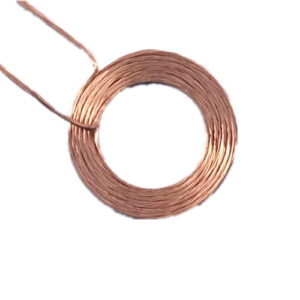
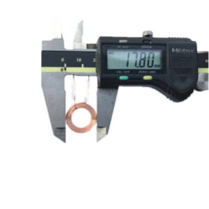
The wireless charging coil in the wireless charger, with the active crystal oscillator outputting square waves, is filtered by a second-order low-pass filter to obtain a stable sine wave output. It is then output to the parallel resonant circuit composed of a transistor 1 3003 and its peripheral circuit, which consists of coils and capacitors, radiating in to provide energy to the receiving part. According to the parallel resonant formula, the matching capacitor C is approximately 140 pF, and the measured wire diameter is 0.5 mm, with a diameter of 7 cm and an inductance of 47 μH, operating at a carrier frequency of 2 Hz. Therefore, the transmitting part selects an active crystal oscillator operating at a frequency close to the resonant frequency to attack the power carrier frequency.
Magnetic resonance charging utilizes electromagnetic resonance for wireless charging. The principle is similar to acoustic resonance, where energy can be transferred as long as the resonance frequencies of the two media are the same. This method provides a charging distance between electromagnetic induction and radio wave-based charging. The advantage is high transmission power, reaching several kilowatts. It can charge multiple devices simultaneously without requiring coil alignment between the devices. However, it has high losses. The farther the distance, the greater the transmission power and the higher the losses. Additionally, the frequency band used must be well protected.