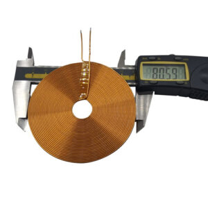
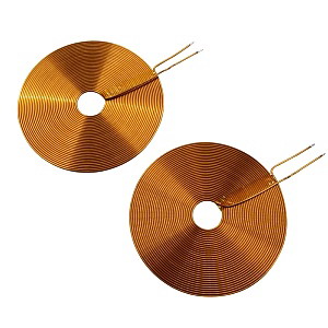
The charging solution for medical inductor coils enables charging for various types of wireless chargers with a conversion efficiency of over 80%. Medical inductor coils are divided into transmitting coils and receiving coils. Transmitting coils are generally thicker, with a thickness ranging from 1mm to 3mm. They have a magnetic shield on the backside and a flat-wound copper coil on top. Multiple fine copper wires are wound and mounted on a composite protective cover. Receiving coils are very thin, typically around 1mm thick, with a magnetic shield on the backside as well. The coil can be flat-wound, flat, or directly made from flexible PCB. Medical inductor coils are certified by the QI international wireless charging standard, providing low-temperature and high safety features. The material selection for medical inductor coils includes the following options.
- Ferrite Medical Inductor Coils and Iron Powder Core Medical Inductor Coils
The inductance of medical inductor coils is directly related to the presence of a magnetic core. Inserting a ferrite magnetic core into a hollow medical inductor coil can increase the inductance and improve the quality factor of the coil.
- Copper Core Medical Inductor Coils
Copper core medical inductor coils are widely used in the ultra-high-frequency range. Changing the orientation of the copper core in the medical inductor coil by rotation can alter the inductance, providing convenience and durability.
- Single-Layer Medical Inductor Coils
Single-layer medical inductor coils are wound with insulated wire on paper tubes and wooden frames. For example, the medical inductor coil used in the wave antenna of a transistor radio.
Medical inductor coils are primarily chosen based on electromagnetic induction principles, utilizing intermittent energy coupling between coils to facilitate energy transfer. During system operation, the input end converts AC mains power into DC power through a full-bridge rectifier circuit or directly supplies the system with 24V DC power. The output DC power, after passing through a power processing module, is converted into high-frequency AC power through inversion by a 2M active crystal oscillator, providing power to the primary winding. Through the coupled energy between two inductor coils, the receiving conversion circuit converts the current output from the secondary coil into DC power for battery charging.